The store will not work correctly in the case when cookies are disabled.
We collect user information to provide a better user experience and protect the security of our website. By continuing to use our website, you acknowledge the use of cookies.
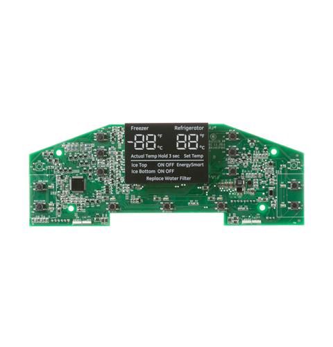
General Electric WR55X11144 Refrigerator PCB Assembly used to control the dispenser, temperature, and user interface of the refrigerator. It has an LED display and buttons or touch controls to ensure easy control and accurate temperature regulation. The board receives inputs from the controls to control the cooling cycles and to achieve better performance and energy consumption. It ensures stable temperature control, minimizes food wastage, and increases the durability of the appliance. The LED display is useful in helping to view the various settings, and the responsive controls are also helpful in their functionality.
Supports the refrigerator's electronic user-interface functions, the General Electric WR55X11144 Refrigerator PCB Assembly LED Icon UI is a circuit-board assembly associated with the LED icon display interface. It provides the electronic interface for presenting designated refrigerator functions or status information through illuminated icons.
LED Icon Display Control
Electronic display signals are handled by the PCB assembly to control the designated LED icon indicators. Individual LEDs are activated according to the refrigerator's electronic control signals and interface configuration.
User Interface Indication
Illuminated icon indicators provide users with a visual reference to designated refrigerator operating information. Their activation and display behavior are determined by the refrigerator’s electronic control system and interface configuration. This arrangement allows selected functions or conditions to be recognized through the refrigerator’s user-facing control area.
Replacement Guidelines:
Replacement may be appropriate when the WR55X11144 no longer performs its intended user-interface function or has damage affecting its operation. The specified part number should be verified against the refrigerator model before selecting a replacement.
Common Failure Symptoms:
LED icons fail to illuminate normally
Individual indicators become unavailable
Display indicators operate intermittently
Designated icons show inconsistent operation
User-interface indications become unavailable
Refrigerator status or function icons are not displayed normally
Visible damage appears on the PCB assembly
Equipment Compatibility:
The General Electric WR55X11144 Refrigerator PCB Assembly LED Icon UI should be matched to the applicable GE refrigerator by verifying the complete refrigerator model number, LED icon user-interface configuration, and manufacturer part number WR55X11144 against the relevant GE parts documentation before purchase.
What maintenance is required for the General Electric WR55X11144 PCB Assembly LED Icon UI?
Keep the PCB and control panel dry and free from dust, liquids, or cleaning chemicals. Make sure connectors are properly seated. Careful handling ensures all icons display correctly, buttons respond to input, and the refrigerator’s systems perform as intended.
What are common issues with the General Electric WR55X11144 PCB Assembly LED Icon UI?
LED icons not displaying correctly.
Buttons unresponsive.
Error codes appearing intermittently.
Incorrect temperature readings or display flickering.
What does a refrigerator UI PCB assembly do?
A UI PCB assembly provides the electronic interface through which designated refrigerator functions, settings, or status information are presented to the user.
Where does a user-interface PCB fit within a refrigerator?
It forms part of the refrigerator’s electronic user-interface system, connecting the user-facing control area with the refrigerator’s electronic control functions.
Can a UI board affect multiple refrigerator controls or indications?
Yes. A single UI board can support multiple designated interface functions when those functions are incorporated into the refrigerator’s specific user-interface configuration.
When should a refrigerator UI PCB assembly be replaced?
Replacement may be appropriate when the board is damaged or when its designated user-interface functions no longer operate normally.
How can GE WR55X11144 be matched when replacing the LED icon display assembly?
Match part number WR55X11144 with the complete refrigerator model number and LED icon user-interface configuration using the relevant GE parts documentation.
Installation Steps
Step1: Unplug the refrigerator to prevent electrical shock.
Step2: Locate the user interface control panel on the refrigerator door.
Step3: Carefully remove the control panel cover.
Step4: Disconnect the wiring harness from the existing PCB assembly.
Step5: Remove the mounting screws and take out the old board.
Step6: Install the new PCB assembly and reconnect the wiring.
Step7: Reattach the panel cover, restore power, and test the display functions.