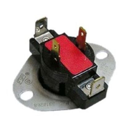
Whirlpool WP8318268 Dryer Cycling Thermostat
$54.49
In stock
Available Quantity:
191
SKU
WP8318268
Product Description
The Whirlpool WP8318268 Dryer Thermostat Fix regulates temperature by cycling the heat on and off for optimal drying. It functions with an internal-bias heater, activating at 155°F and shutting off at 130°F. As air flows through the dryer, the thermostat maintains consistent heat levels, preventing overheating. This ensures efficient drying, reduces energy consumption, and extends the appliance’s lifespan. Reliable temperature control enhances performance while preventing damage to fabrics, making laundry cycles more effective and safe.
Manufacturer

✓ This Product Replaces:
3977706, 3977425, 8318268