The store will not work correctly in the case when cookies are disabled.
We collect user information to provide a better user experience and protect the security of our website. By continuing to use our website, you acknowledge the use of cookies.
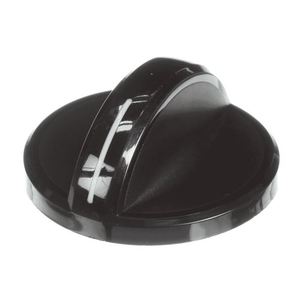
The Whirlpool WP8286057BL is a replacement knob made exclusively for managing the surface burners on your Whirlpool gas range. This knob serves as a conduit between you and the burner, enabling you to control the flame height and turn on and off the gas. Usually, it has numbers or marks that represent the various flame intensities, from low simmer to high heat. A valve that controls the burner's gas flow is opened when the knob is turned. Twisting the knob clockwise reduces the flow for a lower flame or to totally shut off the gas, while twisting it counterclockwise increases the flow for a higher flame.
Step 1: The necessary tools and materials will be assembled. A Phillips-head screwdriver along with the replacement Whirlpool WP8286057BL knob will be required.
Step 2: The old knob will be taken off. The two screws located at the back of the oven will be detached and the old knob will be extracted.
Step 3: The new knob will be attached. The new knob will be positioned in the identical location as the old one, with the two silver posts aligned with the matching slots on the oven panel. The two screws will be firmly tightened.
Step 4: The new knob will be verified. The knob will be rotated to confirm it is securely fastened and operating correctly.
Step 5: Continuation will be made. If additional control knobs require replacement, steps 2 through 4 will be followed until all knobs have been replaced.
Please note that these instructions are served as general guidance and should always be utilized alongside the manufacturer's manual, if available.