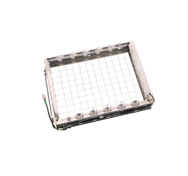
Whirlpool WP2313637 Refrigerator Ice Cutter Grid
Special Price
$137.64
Regular Price
$235.99
In stock
Available Quantity:
92
SKU
WP2313637
Product Description
The Whirlpool WP2313637 Refrigerator Ice Cutter Grid works in a way that it chops the ice cubes into small and equal portions so that it can easily dispense the ice. It is installed into the ice maker system to cut the large ice cubes into smaller sizes to avoid blockage and facilitate the flow of ice.
Manufacturer

✓ This Product Replaces:
2182399, 2185614, 2313601, 2313637