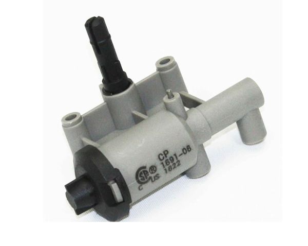
Whirlpool 74002413 Range Igniter
Special Price
$70.65
Regular Price
$127.33
In stock
Available Quantity:
2
SKU
74002413
Product Description
The Whirlpool 74002413 Range Igniter lights the flame to begin the cooking process. It operates by generating a spark component which lights up the gas when the burner knob is switched, providing quick and dependable ignition. This igniter allows stable performance of the flame and safe use in the procedure of cooking. It is fitted in the burner unit within the oven to provide dependable ignition and correct cooking operation.
Manufacturer