The store will not work correctly in the case when cookies are disabled.
We collect user information to provide a better user experience and protect the security of our website. By continuing to use our website, you acknowledge the use of cookies.
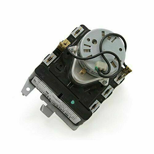
The General Electric WE4M359 Dryer Timer Plastic Shaft transmits rotational input from the user interface to the dryer timer mechanism, enabling control of cycle duration. It mounts there on the control panel, with the timer assembly, clipped or screwed in. The shaft is set to synchronize with the timer mechanism, switches and other related electronics. It allows the proper timing entry, which facilitates drying cycles, operational sequencing and competent dryer operation under normal usage.
Step 1: Preparation for the Repair: Prior to initiating your repair, the dryer should be disconnected from the power source and the gas supply valve should be turned off if applicable. Your tools and materials, which consist of a putty knife, 1/4-inch nut driver, Phillips screwdriver, and a replacement timer, should be assembled.
Step 2: Removing the Cabinet: The screws located at the back of the dryer that secure the top panel should be taken out. After the screws have been removed, the top panel should be elevated and set aside. The putty knife should be utilized to detach the screws that secure the front cover. The front cover should be lifted off the dryer and positioned on a surface that will not scratch or harm it.
Step 3: Locating the Timer: The timer knob situated on the control panel should be identified. This knob is actuated by a shaft linked to the center of the timer. The shaft should be traced back to find the timer. The panel concealing the timer should be detached using your fingers, or any screws that hold it in place should be unscrewed.
Step 4: Removing the Timer: The electrical connections at the rear of the timer that link it to the wiring harness should be unplugged. A nut driver should be used to unscrew the retaining screws that secure the timer. The timer should be extracted once the screws have been taken out.
Step 5: Replacing the Timer: The new timer should be positioned in the identical orientation as the old one, ensuring the plastic shaft aligns correctly. The timer should be fastened with the retaining screws. The electrical connections at the back should be reconnected to the wiring harness. The panel that covers the timer should be replaced.
Step 6: Reassembling the Dryer: The front cover should be reattached on the dryer and secured using the screws. The top panel should be repositioned back onto the dryer, aligning the tabs properly. The top panel should be fastened with the screws. The dryer should be reconnected to the power supply and the gas supply valve should be activated. The dryer should be tested to verify that the timer functions correctly.
Please remember, these instructions serve as general guidance and should always be utilized alongside the manufacturer's manual, if accessible.