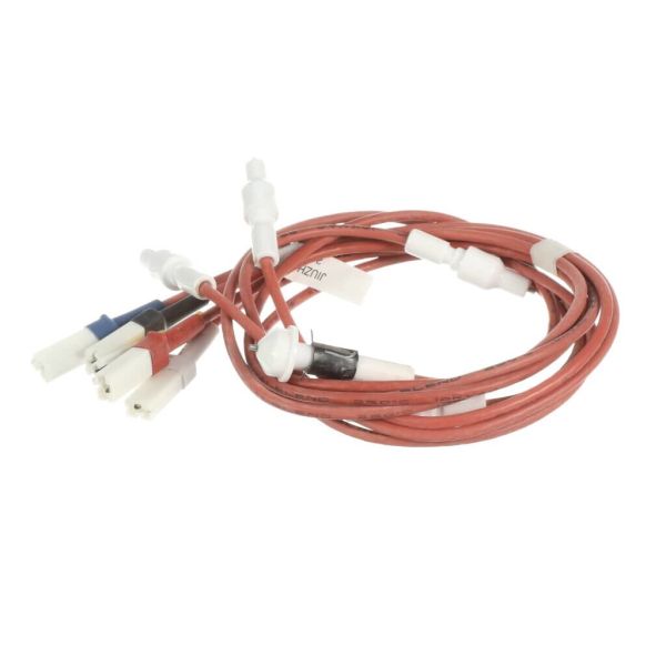
GE WB18X26980 Range High Voltage Electrodes & Harness
Special Price
$46.02
Regular Price
$57.95
In stock
Available Quantity:
44
SKU
WB18X26980
Product Description
ELECTRODES & HARNESS H.V
Manufacturer