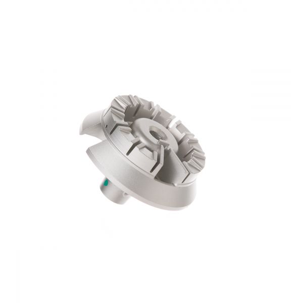
General Electric WB16K10070 Range Small Burner 5K
$28.84
In stock
Available Quantity:
76
SKU
WB16K10070
Product Description
SMALL BURNER V 5K
Manufacturer

✓ This Product Replaces:
WB16K10024