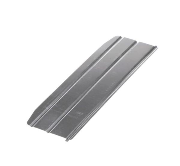
General Electric WB06X10565 Microwave Damper
Special Price
$14.26
Regular Price
$17.88
In stock
Available Quantity:
16
SKU
WB06X10565
Manufacturer