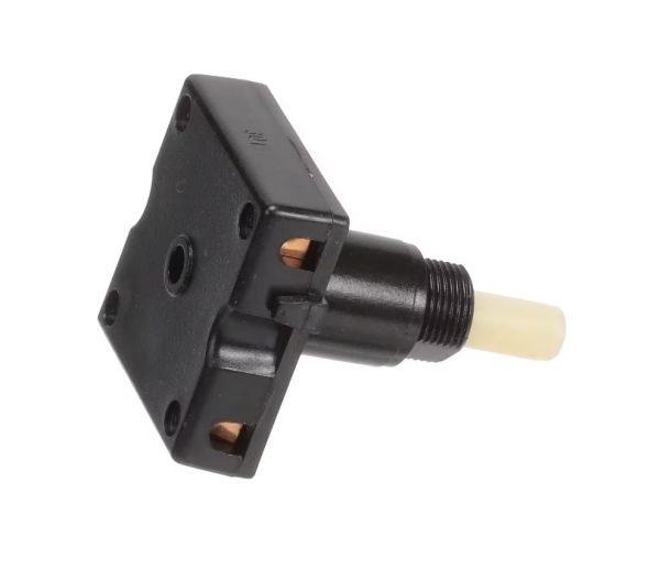
The Whirlpool W11206737 Range Rotary Switch is an essential component used to regulate and control the numerous functions of a range appliance. This switch's basic rotary operation makes it easy for users to change temperature, set a timer, and select cooking modes. It is commonly found in contemporary kitchen ranges, providing users with exact control over cooking procedures for the best outcomes. Its sturdy design guarantees endurance and dependability in operation. By making it easier to operate the range, the switch improves user convenience and facilitates seamless cooking experiences. Cooking is made enjoyable with the Whirlpool W11206737 Range Rotary Switch. It is no longer just a hassle.
Step 1: The appliance should be disconnected from the power outlet and the circuit breaker providing electricity should be turned off.
Step 2: Any screws that are visible, securing the W11206737 SWTCH-ROTR switch should be taken out.
Step 3: The switch should be gently extracted from the appliance and the wires should be detached from the terminals.
Step 4: A replacement switch should be acquired from a certified retailer or manufacturer. The old switch should be brought with you to confirm the correct one is obtained.
Step 5: The wiring of the new switch should be attached to the corresponding terminals.
Step 6: The switch should be reinstalled in its initial position using the screws that were previously removed.
Step 7: The circuit breaker should be reactivated and the appliance should be reconnected to the power outlet.
Step 8: The appliance should be verified to ensure it is functioning correctly.
Please be aware that these instructions serve as general guidance and should always be utilized in conjunction with the manufacturer's manual, if available.