The store will not work correctly in the case when cookies are disabled.
We collect user information to provide a better user experience and protect the security of our website. By continuing to use our website, you acknowledge the use of cookies.
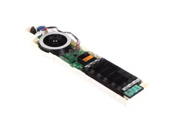
The LG EBR85755505 Display PCB Assembly is responsible for receiving commands from the user and relaying them to the various parts of the washing machine. They take inputs from buttons or touchpad and convert them into electrical signals that control the motor, water inlet and drain system of the washer. This enhances the overall functionality of the system and makes the system to operate and perform efficiently. The assembly helps in controlling the power consumption, increasing the durability of the washer.
Located behind the washer’s control panel, the LG EBR85755505 Washer Display PCB Assembly serves as the electronic interface for user selections and displayed cycle information. This genuine OEM component communicates control inputs to the washer’s electronic system while presenting relevant operating status to the user.
Display Interface Processing:
Button or touchpad selections are received by the display PCB and converted into electronic signals that the washer’s control system can process. This allows user commands to be electronically communicated for the selected washer functions.
Cycle Selection and Status Display:
At the control panel, the display PCB provides the interface through which users select washer functions and view operating information. Its electronic interface connects user selections with the washer’s programmed cycle controls.
Replacement Guidelines:
Replacement of the LG EBR85755505 display PCB assembly may be appropriate when the display remains unresponsive, user controls fail to register commands, or the PCB has visible electronic or physical damage that affects normal interface operation.
Common Failure Symptoms:
Display remains blank or unresponsive
Buttons or touch controls fail to register commands
Cycle selections do not respond normally
Display information is missing or incorrect
Visible damage to the PCB assembly
Equipment Compatibility:
The LG EBR85755505 is a genuine OEM display PCB assembly used in selected LG washer applications. Documented compatible models include WT7800CW, WT7800CV, and WT7800CV/00. Related identifiers include AP6981181, EAP12739072, and PS12739072. Verify the washer model and original PCB identification before selecting the assembly.
What maintenance is required for the LG EBR85755505 Display PCB Assembly?
Keep all connectors secure and free of moisture or debris. Confirm cycle selections register immediately. Verify display updates accurately and all washing functions respond correctly during repeated operation without delayed or skipped commands.
What are common issues with the LG EBR85755505 Display PCB Assembly?
Washer not powering on.
Display panel remaining blank.
Buttons not responding to input.
PCB overheating after extended use.
What does the LG EBR85755505 display PCB control?
The EBR85755505 processes user selections through the washer interface and communicates the selected settings to the washer's electronic control system.
How does the EBR85755505 handle washer control inputs?
The display PCB receives button or touch-control inputs and converts those selections into electronic signals for the washer's control system.
What information can the EBR85755505 display?
The display interface presents selected cycle settings and other operating information to the user during washer operation.
Is the EBR85755505 the same as the washer's main PCB?
No. The EBR85755505 is identified as the display PCB assembly, while the washer's main PCB is a separate electronic board within the appliance.
What can indicate a problem with the EBR85755505?
A blank or unresponsive display, controls that fail to register selections, missing cycle information, or abnormal interface operation can indicate an issue with the display PCB assembly.
Installation Steps
Step1: Disconnect the washer power supply to avoid electrical hazards.
Step2: Remove the top or front control panel cover carefully.
Step3: Unplug all wire harness connectors from the existing display board.
Step4: Unscrew and detach the old PCB from its mounting bracket.
Step5: Install the new display PCB and secure it firmly in place.
Step6: Reassemble panel, restore power, and verify the display operation.