
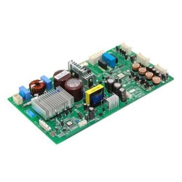
LG EBR86093718 Refrigerator Main PCB

Special Price $297.31 Regular Price $369.95
In stock
Available Quantity:   28
SKU
EBR86093718

Product Description

The LG EBR86093718 PCB Main Control Board controls the operations of the refrigerator, including cooling and power supply. It takes input signals from the sensors and regulates the temperature setting and the compressor operation. It regulates defrost cycles and controls the operations of the fan to maintain the cooling performance and avoid ice formation. It ensures that temperature changes are well regulated to ensure the food is well preserved.
Refrigerator Parts, PCBs,
Manufacturer
https://www.hnkparts.com/media/catalog/product/e/b/ebr86093718_lge_hnkparts.png

This Part Fits the Following Models (2)

Manufacturer Name: LGE
Product Number: EBR86093718
OEM Part Number: EBR86093718
Product Description: Pcb Assy-Main

Choose the best Home Appliance parts and supplies from HnKParts!

  • Same Day Shipping

  • Best Quality And Best Price

  • Wide Range of Inventory

  • Best Customer Service

Have More Questions or Need Help to Place The Order?
Reach us at (866)723-0907 or [email protected]

Write Your Own Review
You're reviewing:LG EBR86093718 Refrigerator Main PCB
Your Rating
Customer Questions
What maintenance is required for the LG EBR86093718 Main PCB?

Regularly inspect the PCB for dust, moisture, or corrosion. Ensure the refrigerator is unplugged during checks. Avoid touching components directly, and keep surrounding areas dry to prevent electrical issues and maintain accurate performance.

What are common issues with the LG EBR86093718 Main PCB?

  • Refrigerator not cooling properly.
  • Erratic temperature readings.
  • Unresponsive control panel or buttons.
  • Frequent defrost cycle problems.
  • Intermittent power failures or system resets.

Installation Steps

Step1: Unplug refrigerator and ensure power is fully disconnected for safety.

Step2: Remove rear access panel to reach control board compartment.

Step3: Disconnect wire harnesses, noting original connector positions.

Step4: Unscrew and remove existing PCB from mounting bracket.

Step5: Install new PCB and reconnect all harnesses securely.

Step6: Refit panel, restore power, and test cooling and control operations.