The store will not work correctly in the case when cookies are disabled.
We collect user information to provide a better user experience and protect the security of our website. By continuing to use our website, you acknowledge the use of cookies.
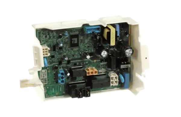
The LG EBR85130512 Dryer PCB Assembly controls the motor, heating elements and other components of the dryer and receives signals from the user interface and regulates the functioning of the machine. This PCB assembly interprets the selected drying cycle into actions, which makes the drying process effective by controlling the heat and air flow. Some of the advantages include energy conservation, the ability to set the drying cycle with high levels of accuracy and durability.
What maintenance is required for the LG EBR85130512 PCB Assembly?
Keep the area around the dryer control board clean and free of lint, dust, and moisture to prevent shorts or overheating. Wipe surrounding surfaces with a dry cloth rather than spraying liquids. Inspect wiring harnesses for secure connections during routine servicing. Always disconnect power before touching the PCB to avoid electrical shock.
What are common issues with the LG EBR85130512 PCB Assembly?
Dryer fails to start cycles.
Buttons or display unresponsive.
Error codes appear unexpectedly.
Settings do not save correctly.
Installation Steps
Step1: Unplug the dryer before servicing.
Step2: Remove the control panel housing to access the PCB.
Step3: Disconnect all wiring harnesses from the old board.
Step4: Install the new PCB assembly and reconnect wiring securely.
Step5: Reassemble the control panel and restore power to test functionality.