The store will not work correctly in the case when cookies are disabled.
We collect user information to provide a better user experience and protect the security of our website. By continuing to use our website, you acknowledge the use of cookies.
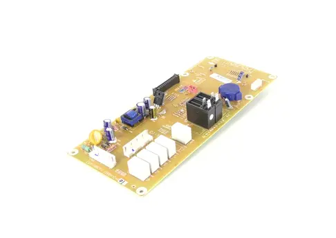
The LG EBR84124401 Microwave PCB Main Control Board controls the heating time, temperature, and power supply among others. It interacts with the other parts of the microwave to regulate the user interface and the overall performance. Due to the accurate working of the PCB, the chances of errors are reduced to the maximum level, and the user interface is smooth.
What maintenance is required for the LG EBR84124401 Main Control Board Assembly?
Keep the board area dry and dust-free. Verify all connectors are firmly attached. Test multiple operations and cooking modes to ensure proper response. Monitor for unusual signals to maintain stable operation across cycles.
What are common issues with the LG EBR84124401 Main Control Board Assembly?
Buttons not responding correctly.
Display showing errors or incorrect status.
Delayed execution of commands.
Settings resetting unexpectedly.
Installation Steps
Step1: Unplug the microwave from the power to ensure safety.
Step2: Remove the microwave outer cover by unscrewing all fasteners.
Step3: Disconnect wires and connectors from the old control board, noting positions.
Step4: Remove the old board and position the new board in place.
Step5: Reconnect all wires securely.
Step6: Reattach the outer cover and screws.
Step7: Restore power and test microwave functions.