
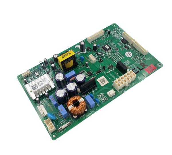
LG EBR80757417 Refrigerator Main PCB Assembly

Special Price $216.32 Regular Price $282.70
In stock
Available Quantity:   27
SKU
EBR80757417

Product Description

The LG EBR80757417 Refrigerator PCB Main Control Board that control and manages the various operations to maintain the right cooling and performance. It controls the electrical signals to regulate the compressor, fans, and the defrost cycle to maintain the temperature. It controls the distribution of power and the diagnosis of systems, improving energy consumption and avoiding problems. This control board also contributes to the longevity of internal parts, energy efficiency, and stable refrigeration.
Manufacturer

✓ This Product Replaces: EBR80757409
https://www.hnkparts.com/media/catalog/productno_selection

This Part Fits the Following Models (1)

MANUFACTURER NAME: LGE
PRODUCT NUMBER: EBR80757417
OEM PART NUMBER: EBR80757417
PRODUCT DESCRIPTION: PCB ASSY-MAIN

CHOOSE THE BEST HOME APPLIANCE PARTS AND SUPPLIES FROM HNKPARTS!

  • SAME DAY SHIPPING

  • BEST QUALITY AND BEST PRICE

  • WIDE RANGE OF INVENTORY

  • BEST CUSTOMER SERVICE

HAVE MORE QUESTIONS OR NEED HELP TO PLACE THE ORDER?
REACH US AT (866)723-0907 OR [email protected]

Write Your Own Review
You're reviewing:LG EBR80757417 Refrigerator Main PCB Assembly
Your Rating
Customer Questions
What maintenance is required for the LG EBR80757417 Main PCB Assembly?

Regularly inspect the refrigerator PCB for dust and moisture buildup, ensuring connections are secure. Use a dry cloth or compressed air to clean gently. Proper maintenance prevents electrical faults, ensures accurate performance, and reduces the risk of short circuits.

What are common issues with the LG EBR80757417 Main PCB Assembly?

  • Refrigerator not cooling properly.
  • Erratic temperature readings.
  • Failure to start or intermittent operation.
  • Display errors or control panel malfunctions.

Installation Steps

Step1: Disconnect power supply and unplug refrigerator.

Step2: Open rear control compartment panel carefully.

Step3: Photograph wiring before removal.

Step4: Disconnect all connectors from old PCB.

Step5: Remove mounting screws and replace board.

Step6: Install new PCB and secure screws.

Step7: Reconnect wiring as per labels.

Step8: Restore power and test operations.