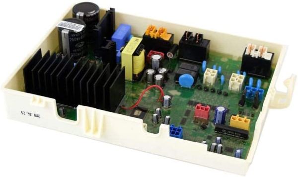
LG EBR79950213 Washer Dryer Main PCB Assembly
Special Price
$352.01
Regular Price
$478.91
In stock
Available Quantity:
24
SKU
EBR79950213
Product Description
The LG EBR79950213 Washer & Dryer Main-Control Board PCB Assembly controls all electrical operations to maintain appliance stability while it combines washing programs with drying modes and temperature settings to achieve effective performance with efficient energy usage. The PCB assembly receives signals from different sensors and buttons before it translates them into activating appropriate functions when needed. The system prevents equipment malfunctions and produces consistent performance for each washing cycle.
Manufacturer