LG EBR76519514 Dryer Main PCB Assembly
Special Price
$240.64
Regular Price
$302.96
In stock
Available Quantity:
38
SKU
EBR76519514
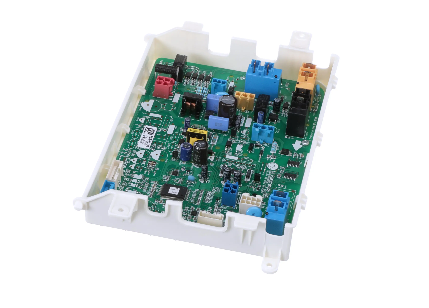
Product Description
The LG EBR76519514 Dryer Electronic-Control Board (PCB Assembly) receives signals from other sensors such as the temperature and moisture sensors and relays the signals to the dryer’s motor and heating coils. It controls the timing and functioning of other dryer parts like the drying cycles and temperatures among others. The advantages of this control board are better performance, accurate cycle control, energy saving, and durability make the users a better experience while using the washing machines.
Manufacturer