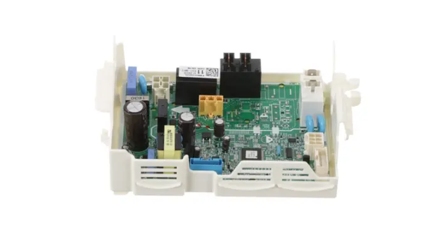
LG EBR31002611 Dryer PCB Assembly
Special Price
$147.67
Regular Price
$217.19
In stock
Available Quantity:
260
SKU
EBR31002611
Product Description
The LG EBR31002611 Dryer Printed Circuit Board Assembly is to regulate the flow of electricity to control the dryer. This component takes information from the sensors and controls and distributes power to various parts of the dryer. It controls heating elements, motors and timers according to the set cycles. It ensures that dryer gets a uniform drying cycle and the performance of the dryer is well maintained.
Manufacturer