
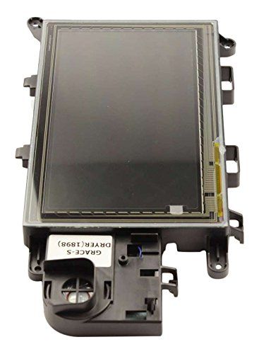
Samsung DC92-01111A Dryer LCD PCB Sub Assembly

Special Price $490.80 Regular Price $629.24
In stock
Available Quantity:   4
SKU
DC92-01111A

Product Description

The Samsung DC92-01111A Dryer PCB-Sub LCD is responsible for regulating and coordinating cycle selection, temperature control, and display interface. The PCB is installed inside the dryer’s control panel and receives input from selected settings and different sensors in the dryer. This data is processed so as to control the motor, heater, and moisture sensors in an efficient and safe way.
Dryer Parts, PCBs,
Manufacturer
https://www.hnkparts.com/media/catalog/product/d/c/dc92-01111a-26952.jpg
Manufacturer Name: Samsung
Product Number: DC92-01111A
OEM Part Number: DC92-01111A
Product Description: Pcb-Sub Lcd

Choose the best Home Appliance parts and supplies from HnKParts!

  • Same Day Shipping

  • Best Quality And Best Price

  • Wide Range of Inventory

  • Best Customer Service

Have More Questions or Need Help to Place The Order?
Reach us at (866)723-0907 or [email protected]

Write Your Own Review
You're reviewing:Samsung DC92-01111A Dryer LCD PCB Sub Assembly
Your Rating
Customer Questions
What maintenance is required for the Samsung DC92-01111A LCD PCB Sub Assembly?

Keep the PCB assembly free from dust and moisture by ensuring the dryer is installed in a dry, well-ventilated area. Periodically inspect connections for corrosion or looseness and secure wiring harnesses properly. Avoid exposure to static electricity or power surges during servicing. Proper handling and clean operating conditions maintain accurate electronic performance.

What are common issues with the Samsung DC92-01111A LCD PCB Sub Assembly?

  • Unresponsive or blank dryer LCD display.
  • Intermittent power or control failures.
  • Button inputs not registering properly.
  • Display flickering or inconsistent readings.

Installation Steps

Step1: Unplug dryer from wall outlet and wait for full discharge to avoid electric shock.

Step2: Remove top panel and control console carefully.

Step3: Disconnect wiring harnesses from old PCB and label connectors.

Step4: Aligning with new PCB connectors and ensuring proper seating.

Step5: Reassemble console and panels securely.

Step6: Restore power and test display operations safely.