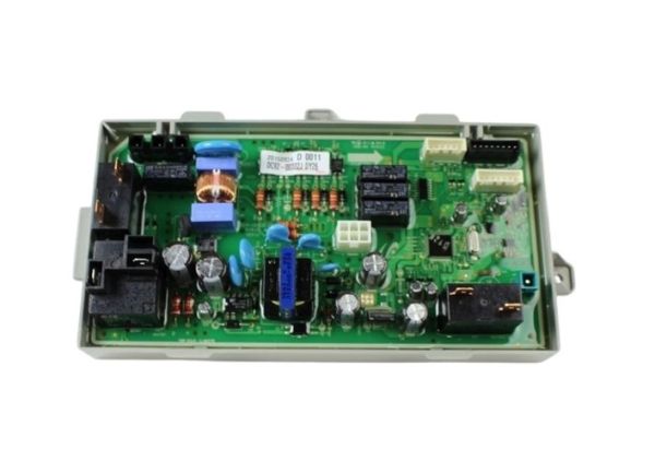
The Samsung DC92-00322J Dryer Main PCB Assembly serves as your dryer's central control unit. The circuit board is intricate and contains the microprocessor and other necessary parts that work collectively to coordinate several dryer functions. The main PCB Assembly is essential to the effective and safe operation of your dryer because it controls the drying temperature and cycle length, monitors sensor data, and connects with other appliance components. When operating properly, this assembly converts sensor readings and user selections into exact actions, which eventually gives your garments the required drying performance. A Main PCB Assembly that is in good working order guarantees ideal drying cycles, helps guard against overheating or under-drying, and extends the life of your dryer overall.
Step 1: The dryer must be disconnected from the electrical outlet. To eliminate the risk of electrical shock, the circuit breakers linked to the dryer must also be deactivated.
Step 2: The dryer’s cabinet panel must be taken off. Typically, a screwdriver will be needed to unscrew the fasteners that are holding it securely.
Step 3: The top section of the dryer must be gently detached from the main unit. If your dryer model comprises two segments, the top section must first be removed and then the back panel must be carefully tilted to extract.
Step 4: After the main housing of the dryer is exposed, the control board assembly must be identified. It is generally situated in the upper-right corner and may be affixed with screws.
Step 5: The screws securing the control board assembly must be taken out with a screwdriver. Subsequently, the complete unit must be extracted.
Step 6: The DC92-00322J Samsung Dryer Main PCB Assembly must be carefully detached from the control board assembly. This component will also have screws that need to be removed.
Step 7: The new DC92-00322J Samsung Dryer Main PCB Assembly must be placed into the control board assembly. It must be ensured that it is securely fastened with the provided screws.
Step 8: The control board assembly must be reinstalled onto the rear of the dryer. It must be confirmed that all screws are tightly fastened.
Step 9: The top and cabinet panels of the dryer must be reattached. The screws that secure these panels must be firmly tightened.
Step 10: The dryer must be reconnected to the electrical supply. The circuit breakers may need to be reset or the dryer may need to be plugged back into the outlet.
Step 11: The functionality of the new DC92-00322J Samsung Dryer Main PCB Assembly must be verified by operating the dryer to ensure proper operation.
Please remember, these instructions serve as general guidance and should always be accompanied by the manufacturer's manual, if one is available.