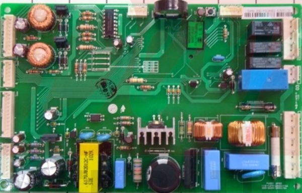
The LG CSP30000202 Refrigerator Onboarding SVC PCB Assembly controls different activities of operations by getting signals from the sensors and passing commands to other parts, such as the compressor, fan and defrost system, to make sure that cooling is done efficiently.
Step 1: Begin by collecting the required tools and materials. This set includes a Phillips head screwdriver, two small flathead screwdrivers, electrical tape, soldering iron, solder, solder wick, desoldering braid, and an anti-static wrist strap.
Step 2: Any power cables linked to the PCB assembly should be detached. This encompasses the main power cord and any peripheral cables associated with it.
Step 3: The retaining screws from the PCB Assembly should be removed, then the assembly should be gently extracted.
Step 4: All other connections to the assembly should be unplugged. These connections may consist of wires, clips, capacitors, or various other components.
Step 5: With a soldering iron and solder, the components from the PCB board should be eliminated. A soldering wick and/or desoldering braid might need to be utilized to assist in this process.
Step 6: After all components have been taken off, the board should be wiped clean using a damp cloth.
Step 7: The new PCB assembly should be positioned correctly and all components should be reconnected.
Step 8: Electrical tape should be employed to fasten and insulate any exposed wires.
Step 9: Any remaining power or peripheral cables should be reattached to the PCB assembly.
Step 10: In conclusion, the retaining screws should be replaced, ensuring the assembly is firmly secured.
It is important to note that these instructions serve as general guidance and should always be paired with the manufacturer's manual, if available.