The store will not work correctly in the case when cookies are disabled.
We collect user information to provide a better user experience and protect the security of our website. By continuing to use our website, you acknowledge the use of cookies.
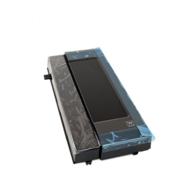
The LG ACM74519108 Microwave Sub Controller Assembly enables major microwave operations by receiving and transmitting signals between the main control board and designated components. As a secondary control unit, it aids in controlling the functions like sensor inputs, display features or door mechanisms, depending on the model. This assembly provides coordination of performance and proper execution of orders. Swapping a faulty subcontroller restores normal internal communication and functionality of compatible LG microwave models.
Step 1: The LG ACM74519108 air conditioner unit is to be disconnected from its electrical outlet.
Step 2: The front panel or door of the unit is to be detached. The front panel or door panel is to be supported while being unfastened from the wall, as it may be heavy.
Step 3: The control assembly is to be identified and all wires linked to the unit are to be detached.
Step 4: The four nuts that secure the control assembly to the wall bracket are to be gently unscrewed.
Step 5: The existing control assembly is to be removed.
Step 6: The new control assembly is to be installed in the same location and aligned with the wall bracket.
Step 7: The control assembly is to be fastened to the wall bracket using the nuts that were previously unscrewed.
Step 8: All wires are to be reconnected to their designated terminals.
Step 9: The front panel or door panel is to be reattached.
Step 10: It is to be verified that all components are correctly installed.
Step 11: The unit is to be reconnected to its electrical outlet.
Please note that these instructions are to serve as general guidance and should always be utilized alongside the manufacturer's manual, if available.