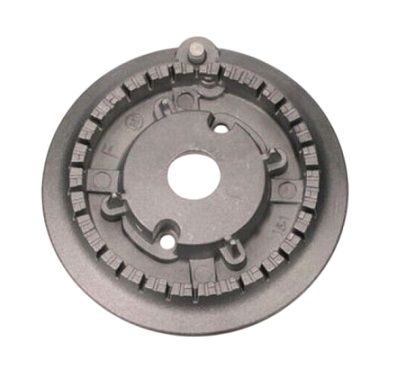
Whirlpool 74007736 Range Surface Burner Head
Special Price
$64.80
Regular Price
$118.42
In stock
Available Quantity:
136
SKU
74007736
Product Description
The Whirlpool 74007736 Range Burner Assembly provide a consistent heat source for cooking appliance by providing a constant flow of heat to the cookware. It is designed to fit compatible models and it can easily be connected to the range to ensure that the temperatures are regulated properly. The assembly work by spreading heat on the burner surface to avoid the formation of hot spots and for effective cooking. This burner assembly enhance the efficiency of cooking, thereby minimizing wastage of energy, and ensuring that the food is well cooked.
Manufacturer