MVI 42242984 30IM Ice Maker SVC Grid Cutter Assembly

Special Price $245.81 Regular Price $292.08
In stock
Available Quantity:   3
SKU
42242984

Product Description

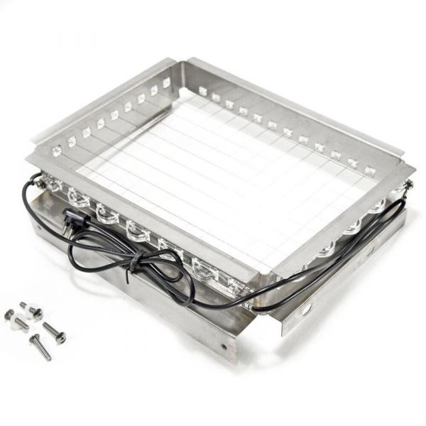
The MVI 42242984 30IM SVC Grid Cutter Assembly is used to cut the ice into the required size and shape fits well on the grid system of the appliance, and comes with sharp and durable cutters for a clean and precise cut. This assembly also optimizes the production of ice, reduces wastage ensures the right shape and size of the ice minimizes the frequency of service, and increases the longevity of the machine, this assembly ensures that works efficiently in providing the right shape of ice for different uses.
Manufacturer
Manufacturer Name: MVI
Product Number: 42242984
OEM Part Number: 42242984
Product Description: Svc Assy 30Im Grid Cutter

Choose the best Home Appliance parts and supplies from HnKParts!

  • Same Day Shipping

  • Best Quality And Best Price

  • Wide Range of Inventory

  • Best Customer Service

Have More Questions or Need Help to Place The Order?
Reach us at (866)723-0907 or [email protected]

Write Your Own Review
You're reviewing:MVI 42242984 30IM Ice Maker SVC Grid Cutter Assembly
Your Rating
Customer Questions
No Questions
Please, mind that only logged in users can submit questions

Installation Steps

Step 1: The power cord is disconnected from the 42242984 SVC ASSY 30IM GRID CUTTER and the power switch is deactivated.

Step 2: A Phillips screwdriver is employed to take out the four screws positioned on the upper section of the machine housing.

Step 3: The top cover is gently raised and set aside.

Step 4: The electrical connections located at the rear of the machine are detached.

Step 5: The four screws that hold the motor in place are removed, then the motor is extracted.

Step 6: The replacement 42242984 SVC ASSY 30IM GRID CUTTER motor is taken and its mounting holes are aligned with those on the machine housing.

Step 7: The new motor is fastened using the four screws that were previously taken out.

Step 8: The electrical connections at the back of the machine are reconnected.

Step 9: The cover is repositioned onto the machine and secured with the four screws.

Step 10: The power cord is reconnected and the power switch is activated.

Please remember, these instructions serve as general guidance and should consistently be utilized alongside the manufacturer's manual, if available.